Figure 1: A Sample SEF document.
Keywords: Geographic Information Systems (GIS), Geography Markup Language (GML), Scalable Vector Graphics (SVG), Schema Mapping, Standard Exchange Format (SEF).
We report our experience in mapping SEF — a data exchange standard for topographic map in Taiwan — to GML. Often there are two goals in such a schematic mapping: Preservation and improvement. That is, the new vocabulary must be used in a way that it losslessly carries over all information that is expressible in the old format, but at the same time opens up opportunities for new functionalities. We discuss in this paper the requirements and design choices we face in mapping the SEF data format to a GML application schema, as well as various visualization issues in a GML-to-SVG mapping. We have built the necessary SEF-to-GML and GML-to-SVG conversion tools, and have used them to process and visualize existing topographic data. Real-world examples are shown in this paper.
1. Motivation
2. An Introduction to SEF
3. Requirements in SEF-to-GML Mapping
4. A GML Application Schema for SEF
5. From GML to SVG
6. Conclusion
Footnotes
Acknowledgements
Bibliography
A major function of Geography Markup Language (GML) is to serve as an intermediate language to facilitate the exchange of information between geographic information systems (GIS). However, there already exist several such intermediate languages. Some of them are mandated by authorities and are often used to access legacy GIS. Standard Exchange Format (SEF), a data exchange standard for topographic maps in Taiwan, is such an intermediate language, and has been mandated as a system requirement in governmental GIS procurements since 1998. A schematic mapping from SEF to GML hence moves the existing GIS bases into XML domains. We report in this paper our experience in converting SEF data to GML documents, with emphases on the requirements and design choices in mapping the SEF data format to a GML application schema, as well as various visualization issues in a GML-to-SVG mapping.
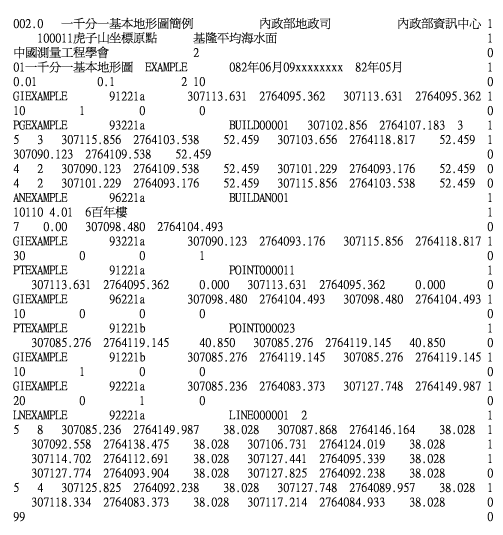
SEF is proposed by the Ministry of the Interior, Taiwan, in 1998 as a data exchange standard for topographic maps. The following is a sample SEF document.
As shown above, SEF uses a fixed-column, FORTRAN-style text format. A text line constitutes a data record and ends with a character '0' at the 80th column. A character '1' at the 80th column indicates the next line is a continuation of the current data record. A geographic feature is expressed as a data record using a predefined record format and feature codebook. For example, the following 5-line data record describes the location of a polygon-shaped concrete wall in the map.
PGEXAMPLE 93221a BUILD00001 307102.856 2764107.183 3 1 5 3 307115.856 2764103.538 52.459 307103.656 2764118.817 52.459 1 307090.123 2764109.538 52.459 0 4 2 307090.123 2764109.538 52.459 307101.229 2764093.176 52.459 0 4 2 307101.229 2764093.176 52.459 307115.856 2764103.538 52.459 0 |
The first two characters of the above data record ('PG') indicate the shape of the feature (polygon). The next 14 characters (column 3-16) indicate the name of the map to which this feature belongs ('EXAMPLE'). Characters from column 17 to 22 denote the stratum code. By the stratum codebook defined by Taiwan's Ministry of the Interior, '93221a' means concrete wall. Column 37 to 46 is an optional external identifier for the feature ('BUILD00001'). It is used to link to an external data source which may contain additional information about the current feature. Following the external identifier in the line is an optional 2-D reference coordinate of the feature which, in this case, is (307102.856, 2764107.183). The shape of each feature is composed by using a fixed set of geometric primitives. In this case, the polygon is composed of 3 primitives (column 73-75) which are expressed by the following lines (character '1' at column 80). The next four lines express a multi-segment line (code '5' at column 1 of line 2) and two single-segment lines (code '3' at column 1 of lines 4 and 5).
We note briefly several drawbacks of SEF.
We consider the following the requirements in our SEF-to-GML schematic mapping.
To convert a SEF file S to a corresponding XML document X,
we first define a schema for X. This schema
contains all the necessary vocabulary so that the
information in the SEF file can be faithfully represented
in the XML document. We have used XML Schema as the
schema definition language, and utilized GML
vocabulary to define an XML schema document,
named sef.xsd, for SEF.
A "GML-ized" SEF file is then an XML document
conforming to this GML application schema.
Instead of giving a full description of sef.xsd in this paper,
we outline in the following the four components in the schema:
title, entities, strata, and features.
The title element in the XML document contains
the various metadata about the map that is already in the SEF file.
The features, strata, and entities
elements are three layers of further abstraction for all the geographic
information in the map.
The features layer is the collection of geographic features ("this line segment denoting a wall", etc.), each the result of converting a SEF record to the corresponding XML element. Each geographic feature is a geometry element (for example, a line segment) with its stratum classification (for example, a wall, which is expressed both as a codebook number and as an optional XLink reference to the corresponding stratum element in the strata layer). The vocabulary for expressing the geometry comes from GML and is an improvement over that in SEF.
The strata and entities layers are optional.
The strata is a tree-structured collection of stratum elements.
Features of the same stratum classification are all referred to within
a stratum element, e.g., wall, in this layer.
Hence, this layer constitutes a structural index (by using the
stratum classification) to all the geographic features in the map.
As a result, we can easily locate all the walls in the map, for example.
The entities layer allows a user to refer to certain features,
strata, and other entities, and to group them together in an
entity element. The entities layer can include
many entity elements. An entity element represents
an object in the application domain (for example, the Institute of Information
Science in a map of Academia Sinica). The entities layer allows users to
locate, in an easy way, all geographic information associated
to an entity in the XML document.
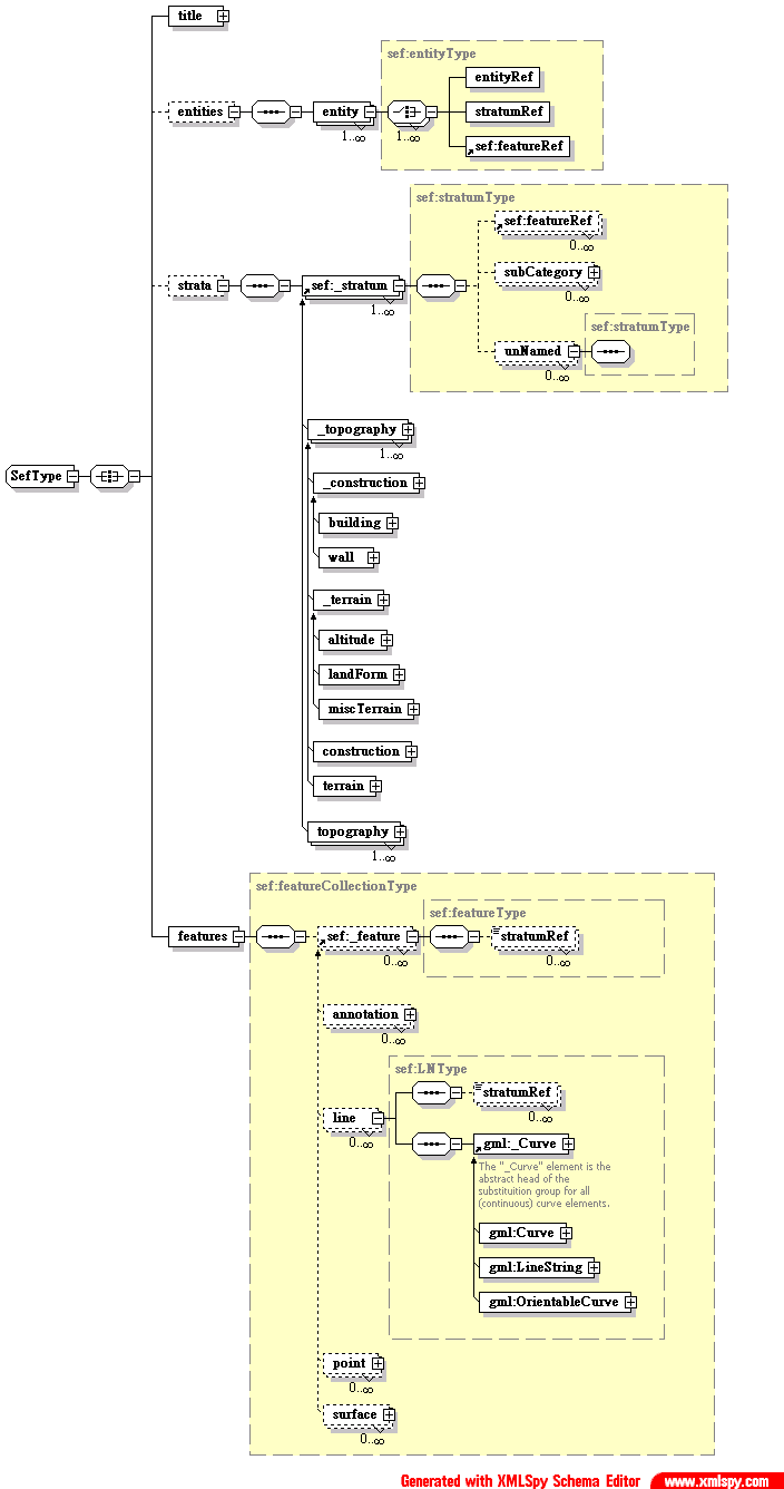
Figure 2
shows a (simplified) diagram illustrating
the structure in sef.xsd, the XML schema document for SEF.
The diagram emphasizes the definitions of entity,
_stratum (the head of a schema substitution group
for stratum elements topography, construction,
building, etc.), and _feature (again, a substitute
group head for feature elements point, line,
surface, etc.).
Note that in
Figure 2
, the abstract stratum element
_stratum has as its children a sequence of featureRef
elements (followed by a sequence of subCategory elements and
another sequence of unNamed elements
[1]
).
Note also that the abstract feature element _feature has
as its children a sequence of stratumRef elements.
A featureRef element is an XLink reference
pointing to a feature element, likewise a stratumRef
element is an XLink reference pointing to a stratum element.
Hence, the two element collections can be used to constitute
inter-layer cross references.
The substitution group relationship in the definition of
strata element may look a little complicated.
Here is a rationale: If an element name starts with
an underscore (e.g., _construction), then it
is an abstract element and its sole purpose
is to serve as the head of a substitution group and acts
as a place holder in the definition of an actual stratum
element type (e.g., construction) so that
its substitution group members (e.g., building and wall)
can appear as its children
[2]
.
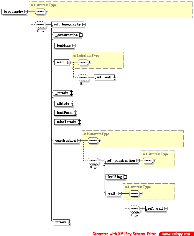
Abstract elements also form substitution group relationship among themselves
so that descendant stratum elements can substitute for ancestor
stratum elements if needed. This is probably better illustrated in
Figure 3
.
The justification for such an "overlay" design of substitution groups is that
it allows both hierarchical and flat layouts in the strata layer.
That is, XML document fragments in
Figure 4
an
Figure 5
are both allowed. This overlay substitution
group design also helps reduce schema size. There are 543 stratum categories in SEF,
and they are arranged in a strict hierarchy. A literal translation of the hierarchy
to similarly structured XML element types will result in a very large schema.
The use of substitution groups allows flexible amendment to
the stratum categorization as well. When a change is needed, we just modify
the substitution relations among the stratum element types, leaving
their content models, stratumType, intact.
A drawback of this flexible design is that one can also
produce highly irregular, but still valid, strata
layers. An example is shown in
Figure 6
.
<strata>
  <topography SID="s9">
     <construction SID="s93000">
        <building SID="s93100">
           <featureRef xlink:href="#S001"/>
           <featureRef xlink:href="#S002"/>
           <featureRef xlink:href="#S003"/>
        </building>
        <wall SID="s93200">
           <featureRef xlink:href="#L001"/>
           <featureRef xlink:href="#L002"/>
        </wall>
     </construction>
     <terrain SID="s98000">
        <altitude SID="s98100">
           <featureRef xlink:href="#P001"/>
           <featureRef xlink:href="#P002"/>
        </altitude>
        <landForm SID="s98200">
           <featureRef xlink:href="#S004"/>
           <featureRef xlink:href="#S005"/>
        </landForm>
        <miscTerrain SID="s98900">
           <featureRef xlink:href="#L003"/>
           <featureRef xlink:href="#P003"/>
        </miscTerrain>
     </terrain>
  </topography>
</strata>
|
Figure 4: A hierarchical layout of stratum elements in the
stratalayer (simplified).
<strata>
  <building SID="s93100">
    <featureRef xlink:href="#S001"/>
    <featureRef xlink:href="#S002"/>
    <featureRef xlink:href="#S003"/>
  </building>
  <wall SID="s93200">
    <featureRef xlink:href="#L001"/>
    <featureRef xlink:href="#L002"/>
  </wall>
  <altitude SID="s98100">
    <featureRef xlink:href="#P001"/>
    <featureRef xlink:href="#P002"/>
  </altitude>
  <landForm SID="s98200">
    <featureRef xlink:href="#S004"/>
    <featureRef xlink:href="#S005"/>
  </landForm>
  <miscTerrain SID="s98900">
    <featureRef xlink:href="#L003"/>
    <featureRef xlink:href="#P003"/>
  </miscTerrain>
</strata>
|
Figure 5: A flat layout of stratum elements in the
stratalayer (simplified).
<strata>
  <topography SID="s9">
    <construction SID="s93000">
      <building SID="93100">
         <featureRef xlink:href="#S001"/>
         <featureRef xlink:href="#S002"/>
         <featureRef xlink:href="#S003"/>
      </building>
    </construction>
    <wall SID="s93200">
      <featureRef xlink:href="#L001"/>
      <featureRef xlink:href="#L002"/>
    </wall>
    <altitude SID="s98100">
      <featureRef xlink:href="#P001"/>
      <featureRef xlink:href="#P002"/>
    </altitude>
    <terrain SID="s98000">
      <landForm SID="s98200">
        <featureRef xlink:href="#S004"/>
        <featureRef xlink:href="#S005"/>
      </landForm>
    </terrain>
    <construction SID="s93000">
      <featureRef xlink:href="#L003"/>
      <featureRef xlink:href="#L004"/>
    </construction>
  </topography>
</strata>
|
Figure 6: An irregular layout of stratum elements in the
stratalayer (simplified).
A complete GML-ized SEF document instance, generated from an existing SEF file (files/5045.sef) by our SEF-to-GML converter, can be found at files/5045.xml. Note that tag names and element content are in Chinese characters. The actual SEF schema use Chinese element names [3] .
Once the GML-ized SEF documents are available, there is a natural need to visualize the geography information in these documents. The visualization process not only serves as a visual validation of the quality of the SEF-to-GML conversion, but also presents us with rich opportunities in exploring visualization issues and techniques.
We have used Scalable Vector Graphics (SVG) as the visual presentation language for GML-ized SEF documents. SVG is a W3C standardization effort for an XML-based vocabulary for vector graphics. It is well supported by the industry, and there exist open source tool kits, e.g., Batik, to render SVG documents and to transform them to other graphics format. By using SVG, we ensure the visual output can be widely used.
However, as SVG is just a visual presentation language,
there remain many presentational and styling decisions to be made
in mapping geographic expressions to visually expressions.
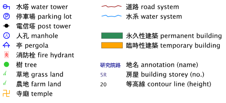
For example, the GML element point does not correspond
directly to any SVG element. A point feature in a SEF document
(and again in the GML-ized SEF document) may indicate a man hole,
a fire hydrant, or a tree — it all depends on the stratum
classification of the feature. We have designed in SVG several
visual symbols for frequently used point features,
see
Figure 7
, so they can be properly displayed.
Likewise, style decisions about line/arc segments have also
been made so that road systems and water systems are visual distinct
in a map. As there are 543 stratum categories in SEF, we must also
decide on what strata to visualize and what else to hide, or rather,
on what GUI mechanisms to be used so that users can freely opt-in/opt-out
the various layers of information and their visual effects.
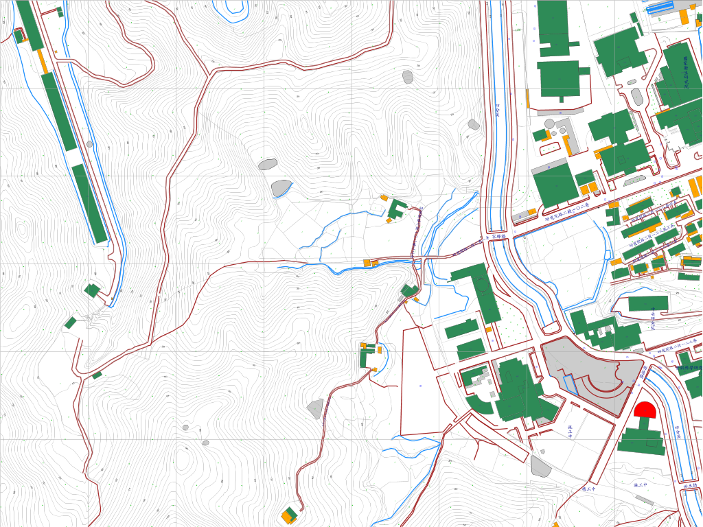
As an example of a rather modest visualization effort, please see Figure 8 for a GML-to-SVG mapping, in which we visualize only buildings, water and road systems, contour lines, and a few kinds of feature points, i.e., essentially those listed in Figure 7 . This is a partial map of Academia Sinica, which is located in the Nangang district of Taipei City, Taiwan. The original SEF document (files/5045.sef), a 1/1000 scale topographic map, is made available to us from the Taipei City government. The GML-ized SEF document can be found at files/5045.xml.
Besides presentational and styling issues, a GML-to-SVG mapping also involves model conversion issue: How to map GML geometry primitives to SVG graphics primitives [4] . We use an example in Figure 8 to illustrate the issue. At the lower right corner of the map, we see a red, approximately half-circle-shaped surface [5] . The SEF feature describes it as a polygon enclosed by connecting the ends of a line segment and two arc segments. (The '5' in the first column of the second line indicates a line segment. The heading '6's in the 4th and 6th lines indicate arc segments. The '3's in column 5 of lines 2, 4, and 6 indicate that each of the three segments is described by 3 control points.)
PG5045 93110 311134.281 2770632.697 3 1 5 3 311121.467 2770626.411 0.000 311146.177 2770623.712 0.000 1 311146.784 2770629.019 0.000 0 6 3 311146.784 2770629.019 0.000 311135.351 2770642.915 0.000 1 311121.849 2770631.020 0.000 0 6 3 311121.849 2770631.020 0.000 311121.699 2770628.712 0.000 1 311121.467 2770626.411 0.000 0 |
This "polygon" can be expressed nicely by a GML surface element as shown below. There is no need to do any model conversion as SEF and GML happen to use the same geometric models: For the line segment they both use linear interpolation, and for arc segment they both use circular-arc-with-three-points interpolation.
<sef:surface sef:FID="id513">
  <sef:stratumRef xlink:href="#s93110"/>
  <gml:Surface>
    <gml:Polygon>
      <gml:exterior>
        <gml:Ring>
          <gml:curveMember>
            <gml:Curve>
              <gml:segments>
                <gml:LineString>
                  <gml:coordinates>
                    311121.467,2770626.411,0.000
                    311146.177,2770623.712,0.000
                    311146.784,2770629.019,0.000
                  </gml:coordinates>
                </gml:LineString>
                <gml:ArcString>
                  <gml:coordinates>
                    311146.784,2770629.019,0.000
                    311135.351,2770642.915,0.000
                    311121.849,2770631.020,0.000
                  </gml:coordinates>
                </gml:ArcString>
                <gml:ArcString>
                  <gml:coordinates>
                    311121.849,2770631.020,0.000
                    311121.699,2770628.712,0.000
                    311121.467,2770626.411,0.000
                  </gml:coordinates>
                </gml:ArcString>
              </gml:segments>
            </gml:Curve>
          </gml:curveMember>
        </gml:Ring>
      </gml:exterior>
    </gml:Polygon>
  </gml:Surface>
</sef:surface>
|
However, to convert the above GML geometry expression to a corresponding SVG element, one needs to adopt an elliptical-arc-with-radii-and-rotation model for the arc segment. This results in the following SVG element, whose closed path defines the same surface. There are other GML geometry primitives which may need similar geometric translations when converted into SVG. We conclude this section by noting that GML and SVG use different coordinate systems and this requires additional translation work in a GML-to-SVG mapping.
<g id="id513">
  <path class="SF93110"
    d="M 311121.467,2770626.411
       L 311146.177,2770623.712
       L 311146.784,2770629.019
       A 12.5147  12.5147  0 1 1 311121.849,2770631.02
       A 64.99423 64.99423 0 0 0 311121.467,2770626.411
       Z"/>
</g>
|
We retrofit SEF, an existing data exchange format for topographic maps, to XML using GML, hence move the existing GIS bases into XML domains. We have taken a moderate approach where only a limited subset of GML vocabulary is used to model SEF geometry features. The experience so far has been rather successful: The information in a SEF document is losslessly preserved in XML using the GML vocabulary, and the resultant GML document is rendered by a visual mapping from (a subset of) GML to SVG.
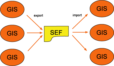
We conclude this paper by using the following three diagrams to show where we are and where we are heading to. The following diagram is the current status of SEF.
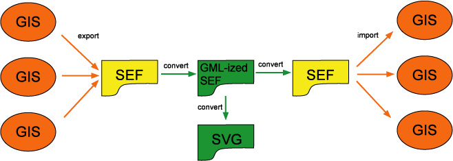
The following is what we have done to SEF.
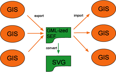
And this is what we hope we are heading to.
Note that the parts in red (various GIS and the export/import arrows) are efforts from GIS providers and are beyond our control. The parts in yellow (the SEF standard) are supported by GIS providers in Taiwan. The parts in green, i.e., what we have done, are independent of GIS providers but lever their previous efforts on SEF. In order to get to where we hope to go (the last diagram), however, need efforts from GIS providers in Taiwan. What we are have done is to experiment and validate the idea of a GML-based intermediate language that accommodates and improves existing SEF functionalities. Now that it proves to be rather successful, we may have a good case to convince the authority to use a GML-based approach and, perhaps, it will in turn mandate GIS providers in Taiwan to support a GML-based intermediate language as well.
subCategory and unNamed elements are SEF peculiarities for
feature categorization and naming which we will not go into details here.
_Curve, LineString,
and OrientableCurve)
[GML]
.
We would like to thank our colleague Jan-Li Lin for his help in the mathematical formulations of some GML to SVG geometric mappings. The work reported here is supported, in part, by the National Science Council of Taiwan (contract no. NSC-91-2219-E-001-005), and by the Institute of Applied Science and Engineering Research, Academia Sinica, Taiwan.
XHTML rendition created by gcapaper Web Publisher v2.0, © 2001-3 Schema Software Inc.